September 28, 2023
What Is the Science Behind Push Button Switches and How They Work
Share
BuildWithFlux


A curated collection of PCB and hardware projects crafted by our talented Flux community.
A push button switch is a simple yet versatile electrical switch used to open or close an electrical circuit by pressing a button. These switches come in various shapes and sizes, but they all share the same fundamental principle: pressing the button changes the switch's state from open to closed or vice versa. This action, often accompanied by a satisfying click, completes or breaks an electrical path, enabling or disabling a device's function.

Understanding how a push button switch works requires a closer look at its internal components. Here is a simplified breakdown:
Push button switches can vary significantly in their configurations, and understanding these distinctions is crucial when designing electronic circuits. Here are some common types:
The SPST push button switch is our first type of single pole switch. It is the simplest type, featuring only one set of contacts—ideal for basic on/off functions and is often found in household light switches.
An SPDT push button switch, another single pole switch type, offers two sets of contacts, allowing it to act as a toggle switch between two different electrical paths. This is useful in scenarios where you need to choose between two actions with a single button press.
DPST push button switches have two sets of contacts, each operating independently. They are commonly used in situations requiring two separate circuits to be controlled simultaneously.
Push button switches can be further categorized as latching or momentary. Latching switches maintain their state after being pressed, while momentary switches return to their original state when released. These distinctions are important depending on the intended function of the switch.
One common issue with push button switches is debouncing. When you press or release a button, it can create rapid fluctuations in the electrical signal due to the mechanical nature of the switch. This bouncing generates a series of electrical spikes and dips, making it challenging for the connected circuitry to interpret the intended input accurately. Debouncing is the process of filtering out these erratic signals to ensure a clean and stable transition between states. Achieving this involves employing techniques such as:
In scenarios where users might rapidly press a button, it's essential to filter out unintended or extraneous signals. This can be achieved through electronic circuitry that detects and ignores rapid successive button presses, ensuring that only intentional inputs are registered. Here's how it works:
Pull-up and pull-down resistors play a crucial role in pushbutton switch circuits, especially in microcontroller-based designs. These resistors are used to ensure that the input signal to the microcontroller is in a known state when the button is not pressed.
We see pull-up and pull-down applications in software as well when we set default values or states for variables, flags, or configuration options—specifying how a particular variable or option should behave when it is not explicitly set.
Push button switches find applications in various domains:
In electronic schematics, push button switches are represented using specific symbols. The most common symbols for push buttons include:

Whether you're turning on a light, starting your car, or operating heavy machinery, push button switches play a crucial role. Understanding their science and functionality is essential for anyone working with electronic circuits. So now next time you press that unassuming button, you can understand the intricate science behind it.
A push button switch is a simple yet versatile electrical switch used to open or close an electrical circuit by pressing a button. These switches come in various shapes and sizes, but they all share the same fundamental principle: pressing the button changes the switch's state from open to closed or vice versa. This action, often accompanied by a satisfying click, completes or breaks an electrical path, enabling or disabling a device's function.
Understanding how a push button switch works requires a closer look at its internal components. Here is a simplified breakdown:
Push button switches can vary significantly in their configurations, and understanding these distinctions is crucial when designing electronic circuits. Here are some common types:
The SPST push button switch is our first type of single pole switch. It is the simplest type, featuring only one set of contacts—ideal for basic on/off functions and is often found in household light switches.
An SPDT push button switch, another single pole switch type, offers two sets of contacts, allowing it to act as a toggle switch between two different electrical paths. This is useful in scenarios where you need to choose between two actions with a single button press.
DPST push button switches have two sets of contacts, each operating independently. They are commonly used in situations requiring two separate circuits to be controlled simultaneously.
Push button switches can be further categorized as latching or momentary. Latching switches maintain their state after being pressed, while momentary switches return to their original state when released. These distinctions are important depending on the intended function of the switch.
One common issue with push button switches is debouncing. When you press or release a button, it can create rapid fluctuations in the electrical signal due to the mechanical nature of the switch. This bouncing generates a series of electrical spikes and dips, making it challenging for the connected circuitry to interpret the intended input accurately. Debouncing is the process of filtering out these erratic signals to ensure a clean and stable transition between states. Achieving this involves employing techniques such as:
In scenarios where users might rapidly press a button, it's essential to filter out unintended or extraneous signals. This can be achieved through electronic circuitry that detects and ignores rapid successive button presses, ensuring that only intentional inputs are registered. Here's how it works:
Pull-up and pull-down resistors play a crucial role in pushbutton switch circuits, especially in microcontroller-based designs. These resistors are used to ensure that the input signal to the microcontroller is in a known state when the button is not pressed.
We see pull-up and pull-down applications in software as well when we set default values or states for variables, flags, or configuration options—specifying how a particular variable or option should behave when it is not explicitly set.
Push button switches find applications in various domains:
In electronic schematics, push button switches are represented using specific symbols. The most common symbols for push buttons include:
Whether you're turning on a light, starting your car, or operating heavy machinery, push button switches play a crucial role. Understanding their science and functionality is essential for anyone working with electronic circuits. So now next time you press that unassuming button, you can understand the intricate science behind it.


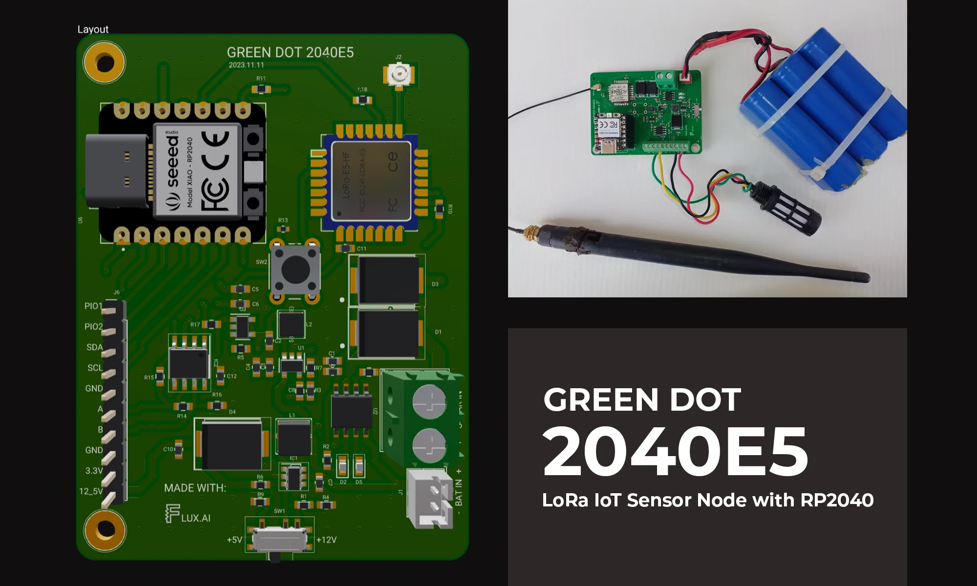
The blog details the creation of a LoRa IoT sensor node for agriculture, focusing on PCB design, power management, wireless connectivity, and sensor integration using the RP2040 microcontroller. It aims to bridge the technology gap in farming, enhancing productivity through data-driven insights.

We're excited to unveil our Smart Polygon system in Flux! This powerful capability builds on top of our automatic copper fills to transform how you create and manage custom copper areas in your PCB designs.
Streamline PCB development with NextPCB templates in Flux, featuring pre-set constraints, AI-assisted layouts, and seamless manufacturing transitions.
If you’re using EasyEDA and are thinking of making the switch to Flux, learn how the two platforms differ and why Flux might be the next step in elevating your PCB design experience.

Electronics, whether in a phone or an industrial motor, face potential threats from unchecked electrical currents. Our guide introduces protection circuits, the essential safeguards that monitor and respond to such electrical anomalies.

We want to make this process as easy as possible for all Flux users. So, after hundreds of hours of testing and talking to dozens of real users, we’ve put together six prompting tips that will help you get the most out of Copilot. Read on to learn more!

The guide provides an easy-to-follow formula for converting mm to mils, essential in engineering and PCB design for precise measurements and applications.

Explore more than 20 new Flux Copilot prompts for hardware design. Accelerate brainstorming, component selection, validation and design review to streamline your PCB design.

The blog offers an in-depth look at Zener diodes, highlighting their crucial role in voltage regulation and stability in electronic circuits. It covers their basic principles, applications, and the challenges faced in their usage.

This post explains key signal integrity issues like crosstalk and reflections in PCBs and offers simple layout tips to avoid them. A free guide is included.

Arduino and Raspberry Pi are two of the most popular single-board computers used by electrical engineers for various projects. Both have their own strengths and weaknesses, and choosing between the two depends on the specific requirements of a project.
Arduino Nano R4 packs UNO R4 performance into Nano size. Learn specs, standout features, and who should upgrade in this in-depth guide.